







- A +
- A
- A -
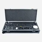
The service recipient in this project is a supplier of tooling for electronic manufacturing. The requirement is to perform full‑dimension 3D scanning and reverse modeling for the mass‑produced modular spliced PCB test fixture. As the core tooling for functional testing of PCBs on electronic production lines, this fixture adopts a multi‑section modular splicing structure. It integrates high‑precision positioning holes, assembly reference surfaces, and special‑shaped hollow stations. It is an essential custom‑made tooling for the ICT/FCT testing of circuit boards on SMT production lines. The client’s key requirement is to obtain accurate 1:1 3D data of the fixture and then reconstruct the CAD model through reverse engineering. The outcomes will be applied for tooling replication, structural optimization and subsequent iterative design, so as to resolve the production pain point caused by the unavailability of original design drawings.

Physical picture
The jig contains a large number of tiny positioning holes, irregular spliced mating surfaces and assembly tolerance features. Traditional manual caliper / CMM measurement can only obtain discrete dimensions and cannot fully reconstruct the 3‑D geometry of complex structures, which tends to result in splicing misalignment and inaccurate positioning after reproduction. Without standardized drawings, there is no accurate data to support the iteration and reproduction of tooling. The surveying efficiency is low, and the assembly consistency after reproduction is poor, which impairs the testing accuracy of the production line.

On‑site scan image
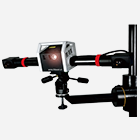
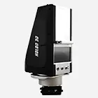
Holon engineers use an industrial‑grade handheld 3D scanner to complete full‑surface point cloud acquisition of the fixture within 10 minutes. All positioning holes, hollow workstations and mating joint surfaces are fully covered. With an accuracy of ±0.02 mm, every tiny feature is reconstructed without blind spots. Based on the scanned point‑cloud data, a reverse‑engineered 3D CAD model that is perfectly consistent with the physical part is generated. All assembly datums, tolerance features and mating relationships are fully retained. The model can be directly interfaced with CNC machining equipment. The final delivered 3D model enables tooling structure optimization (such as weight‑reduction design and workstation expansion), rapid 3D‑printed prototyping, and traceability for mass production. It provides a complete digital foundation for the customer’s subsequent tooling iterations and shortens the tooling replication cycle from 7 days to 2 days.

Reverse modeling diagram