



- A +
- A
- A -
A client visited our facility with a physical sample of an aerospace sheet metal welded component, requiring 3D inspection of the finished part. The process involved comparing the physical sample against the original design CAD model regarding various geometric dimensioning and tolerancing (GD&T) parameters, verifying the actual quality following sheet metal bending and welding, and identifying issues such as welding deformation, profile deviations, and hole position errors. Hualang 3D engineers utilized a handheld scanner to carry out the complete inspection to verify whether the part met the precision requirements for aerospace assembly.
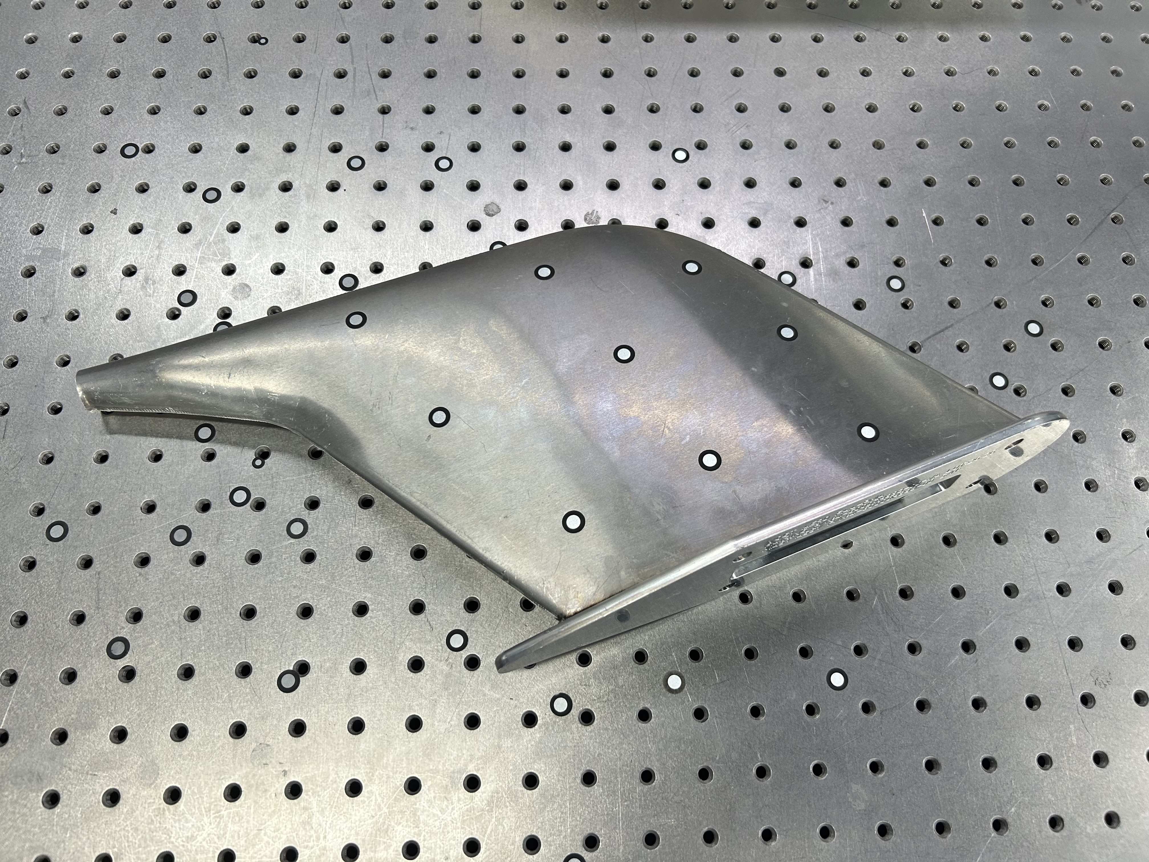
The existing CMM inspection method was limited in the number of points it could measure; inspecting a single part in its entirety was time-consuming, and overall efficiency was low, making it difficult to meet the demands of batch inspection. The client sought a high-efficiency inspection solution and required on-site testing to verify the equipment's actual accuracy and confirm the reliability of the form and position tolerance data derived from 3D scanning before proceeding to actual production.
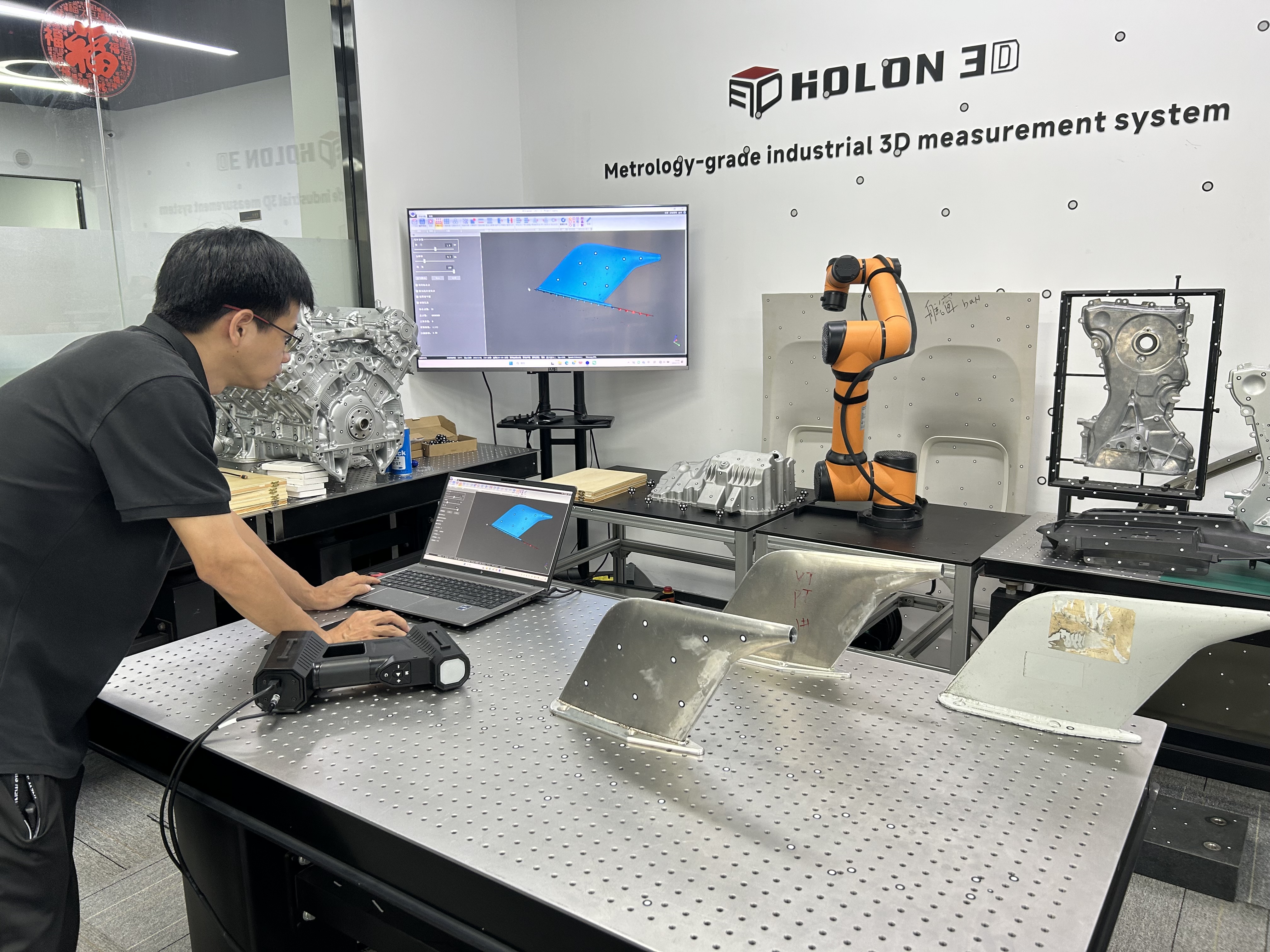
现场图
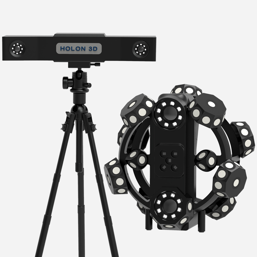
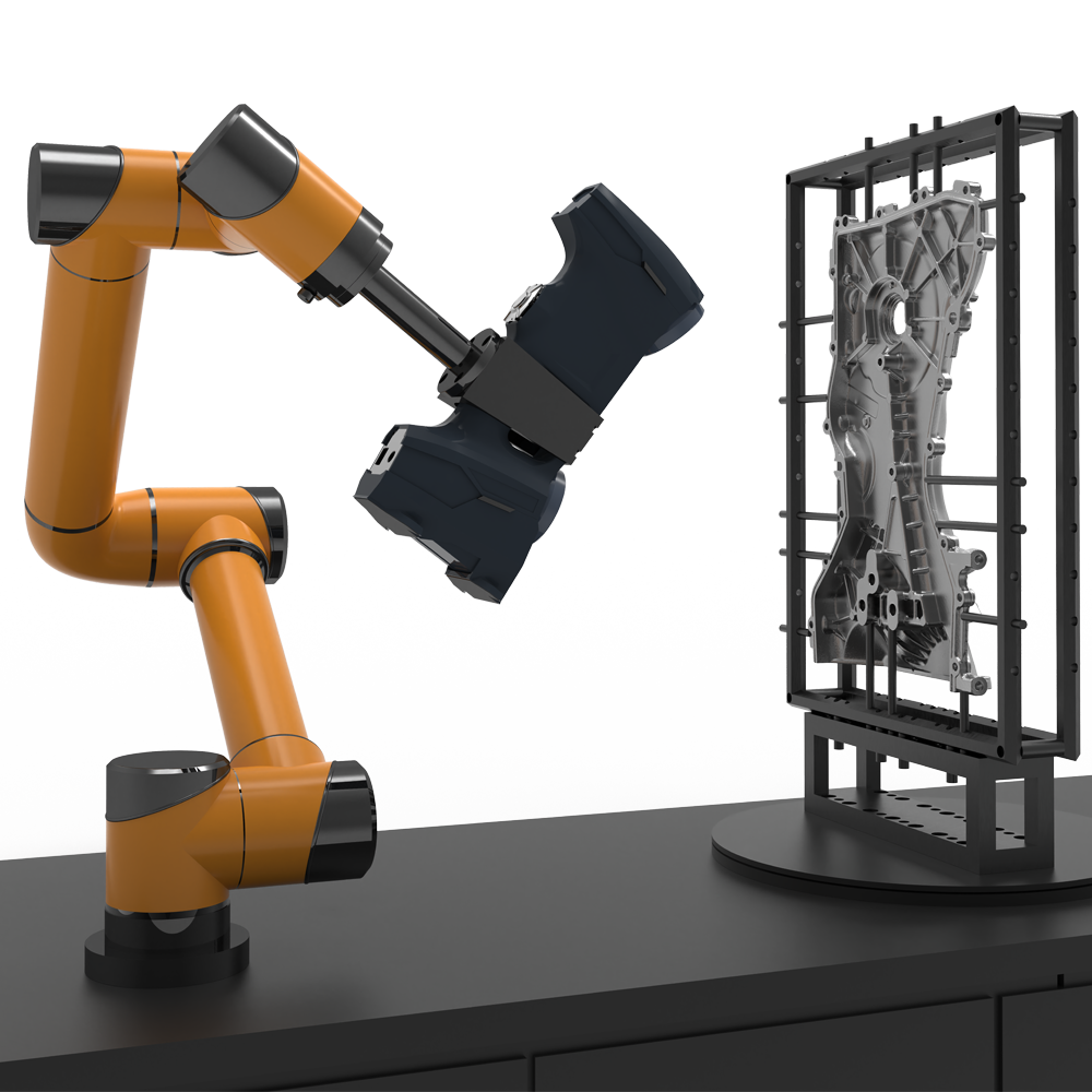
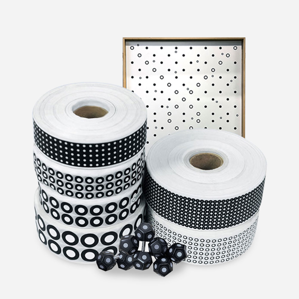
HOLON 3D scanners are used to perform non-contact scanning and inspection, achieving a scanning rate of 4.2 million points per second and an accuracy of up to 0.02 mm. By utilizing reference markers for workpiece positioning—eliminating the need for custom fixtures or gauges—the system rapidly captures complete 3D point clouds of sheet metal parts, ensuring full coverage of curved surfaces, positioning holes, and weld seams.
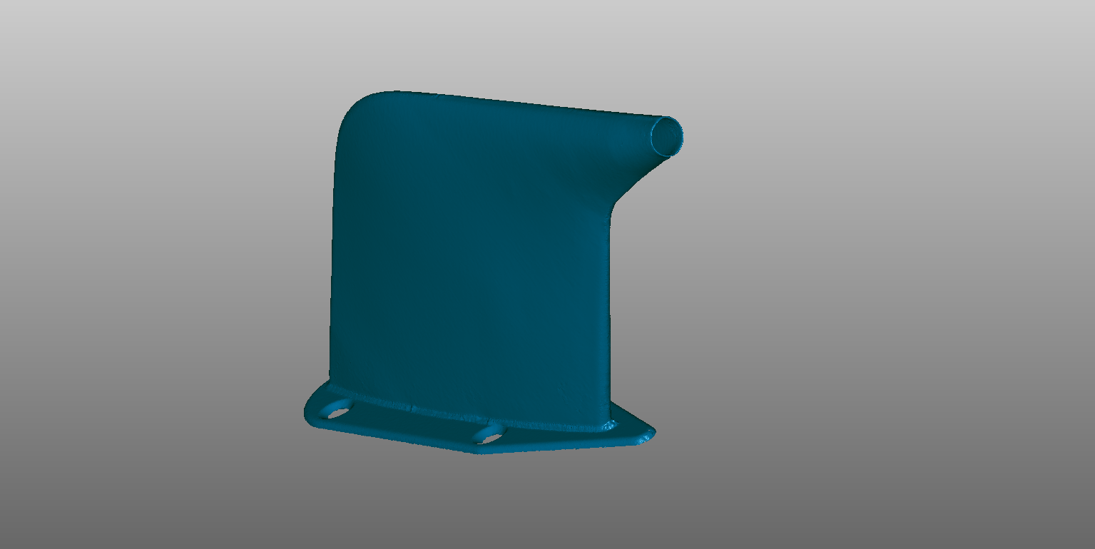
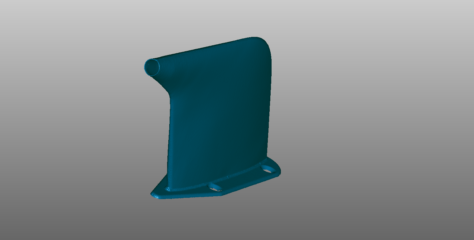
Scanned data model (STL)
Import the scanned point cloud data of the physical part into the inspection software and align it with the original CAD model provided by the client for comparison:
1. Generate a color-coded deviation map to intuitively visualize the overall deformation and out-of-tolerance areas of the welded sheet metal assembly.
2. Calculate and output a complete set of geometric dimensioning and tolerancing (GD&T) data—such as hole diameters, hole positional accuracy, and surface profile—with a single click.
3. Produce a standardized inspection report that cross-references the 3D scanning results with measurements obtained using the client's traditional gauges, thereby verifying the equipment's inspection accuracy on-site.
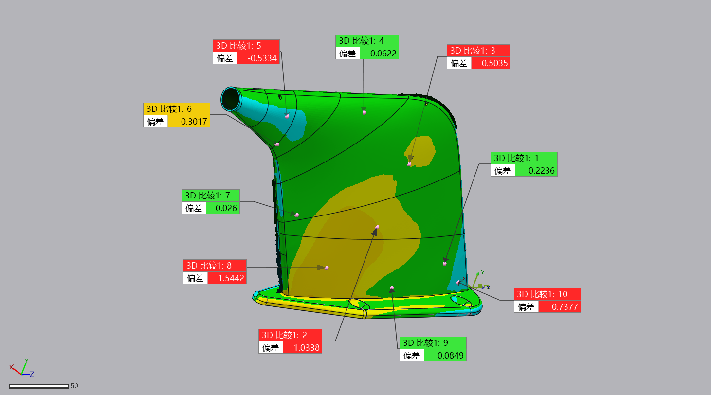
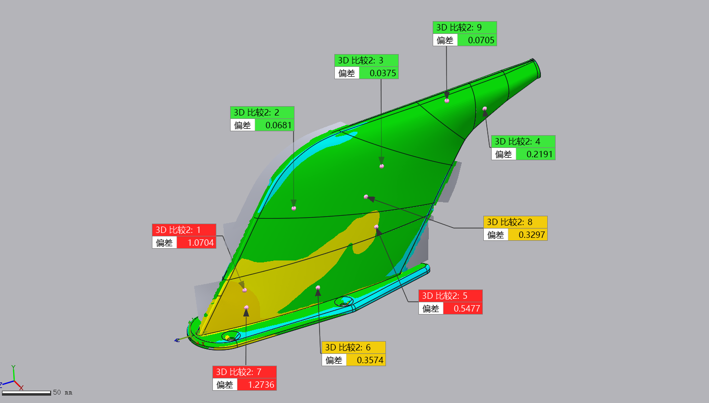
Deviation chromatogram
On-site testing has verified that 3D scanning significantly shortens the inspection cycle per unit and effectively boosts inspection efficiency. The measured data aligns with the client's reference data, confirming the equipment's reliable precision; it accurately captures form and position tolerance deviations between the finished product and the digital model, providing valid, empirical data to support the client in selecting equipment for subsequent mass inspection and optimizing sheet metal welding processes.
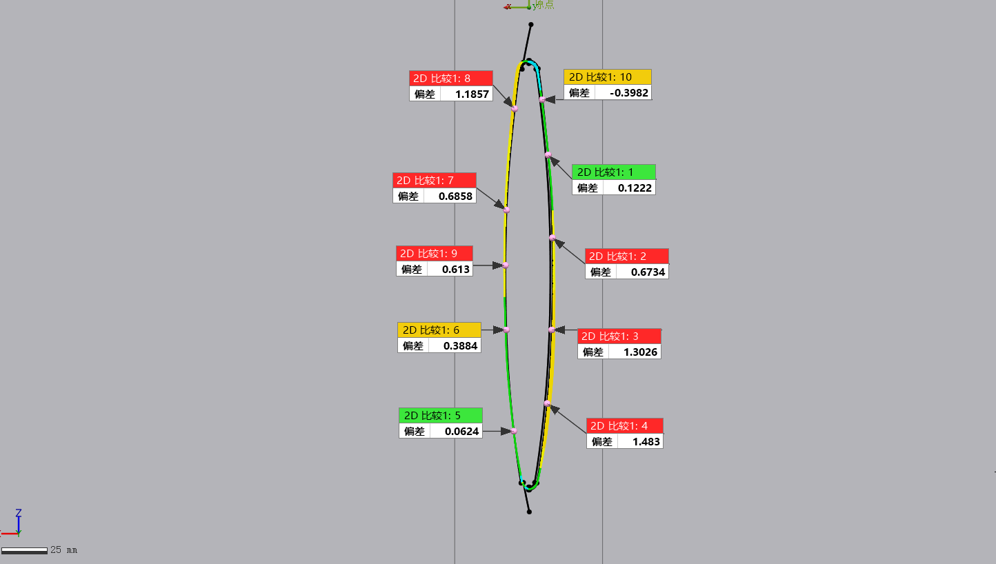
Section view