







- A +
- A
- A -
As the structural carrier of an acoustic system, the speaker enclosure’s curved surfaces, mounting clip positions, chamfer radii and sealing‑groove contours directly affect the positioning accuracy of loudspeakers, the airtightness of the cabinet, and the overall assembly quality of the finished product. As consumer electronic products impose increasingly higher requirements on sound quality and appearance, enclosure designs have become more complex and personalised. Customers need to conduct comprehensive 3D inspection on injection‑moulded or metal speaker enclosures. By comparing the scanned data against the original CAD model, they can quantitatively evaluate the overall deformation and the deviation distribution on key mating surfaces, so as to ensure that the products satisfy the requirements for acoustic design and production‑based assembly.
Limitations of traditional inspection methods: When using calipers, gauges or coordinate‑measuring machines, it is difficult to quickly and completely acquire the overall curved contour of the housing. In particular, fine features such as internal snap positions, the height of screw posts, and sound‑outlet hole grids cannot be subjected to comprehensive and efficient quantitative analysis.
Difficulty in quantifying deformation and assembly deviations: Injection molding or stamping processes may easily cause warpage, shrinkage or local deformation of the housing, which further affects the precision assembly with internal electronic components and the front cover.

On‑site 3D Scanning Photo
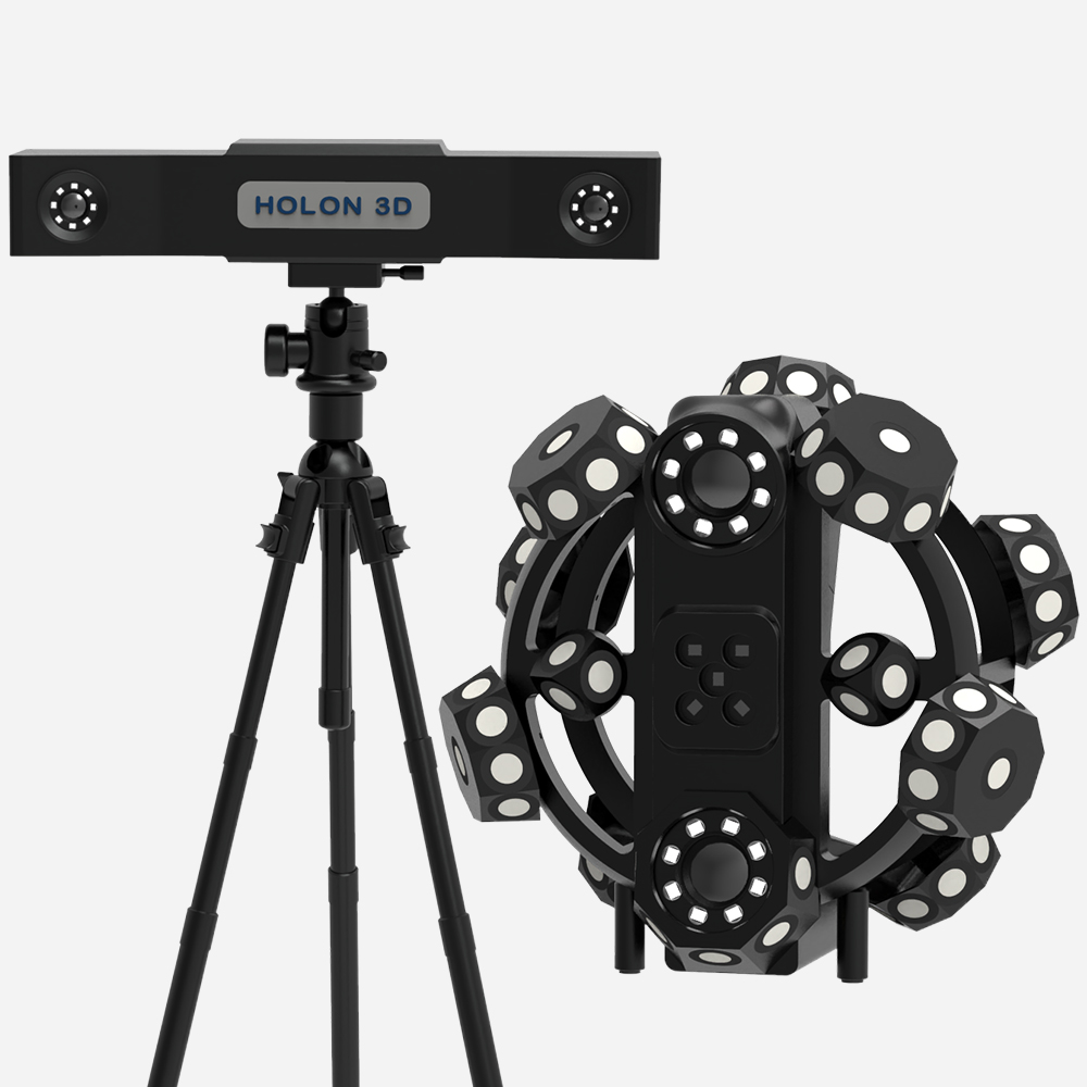
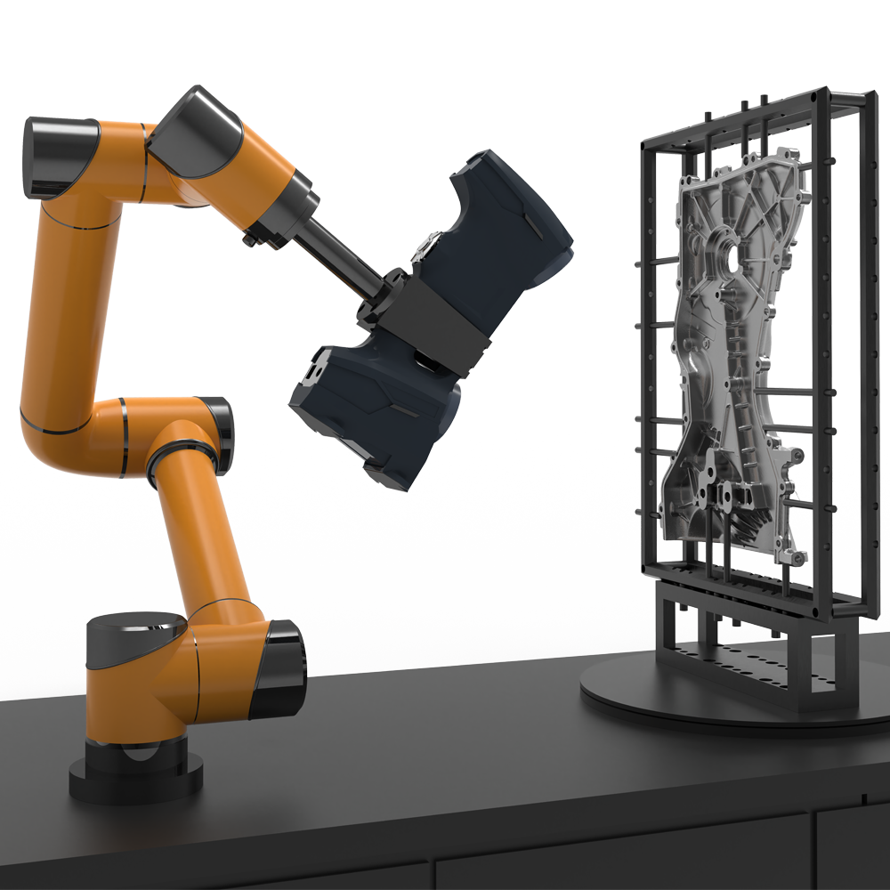
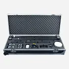
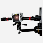
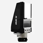
Adopting the HOLON3D handheld full‑blue‑laser industrial‑grade 3D scanner, which features flexible operation and portability. It efficiently captures all fine features including the outer curved surface of the housing, internal snaps, screw bosses, and sealing grooves at a speed of 4.2 million points per second. Compare the scanned data with the original model, and generate a global deviation chromatogram with one‑click operation (deviation distribution is displayed intuitively in red/blue/green) to quantify the overall deformation, profile tolerance of mating surfaces, positional tolerance of snaps, and dimensions of sealing grooves. It is highly suitable for scenarios such as mold trial runs, random on‑production‑line inspections, and incoming material inspection.

Point cloud model
Point cloud model

3D‑Detection Chromatogram‑Front View

3D‑Detection Chromatogram‑Side View